Stellar Furnace / Preliminary design study
SF-1
Repetitive dense-plasma-focus power unit
A proton–boron power unit with direct electrical recovery from charged reaction products. Nominal duty: forty megawatts net.
Design status. The quantities below define a proposed operating point. Integrated operation in this regime has not been demonstrated. The principal unresolved result is positive complete-cycle engineering gain; sustainable repetition, conversion performance and the installed plant mass must also be established.
Specified / Nominal design point
The core allowance excludes the external pulse-power plant, shielding, heat-rejection equipment and service infrastructure. It is not a closed installed mass statement.
01 / Requirements
Convert a sequence of fusion pulses into continuous electrical duty
The unit is conceived as a coaxial discharge assembly coupled to a charged-particle collector and electrical converter. The intended plant supplies power through a conditioned DC link. The repetitive pulse system, rather than the existence of a single fusion event, determines whether the stated duty can be sustained.
- Required transformation: electrical drive prepares a dense reacting plasma; nuclear reactions produce energetic alpha particles.
- Energy recovery: a controlled fraction of the charged products reaches a converter and is decelerated into an electrical load.
- Operating envelope: pulse current, plasma composition, product distribution, converter acceptance and chamber reset must be compatible at the same repetition rate.
- First numerical bottleneck: recovered electricity must exceed all electrical energy consumed over a complete operating cycle.
- Experimental consequence: establish that balance at a measured duty and lifetime before scaling the net output.
At the nominal rate, the complete cycle is 20 microseconds. A 40 MW net duty requires 800 joules net per cycle. A short pinch duration alone does not establish either requirement.
02 / Physical basis
The reaction is observed. The power-unit integration remains to be established.
The principal reaction releases approximately 8.7 MeV in total, predominantly as the kinetic energy of three alpha particles. This is not 8.7 MeV per alpha. Their energies form a distribution determined by the reaction channels and kinematics, rather than three identical monoenergetic beams.
| Category | Established basis | What it does not establish |
|---|---|---|
| Observed physics | Proton–boron reactions measured in the Large Helical Device, using energetic hydrogen beams and boron injection. | Net energy gain, an SF-1 discharge, or high-duty electrical production. |
| Observed plasma-focus behavior | High-energy ions and fusion reactions measured in a dense plasma focus. That experiment used deuterium. | A deuterium result is not a demonstrated proton–boron power balance. |
| Established technology | Capacitor-bank discharges, plasma diagnostics, vacuum systems, magnetic optics and electrical power conversion are available engineering methods. Plasma direct converters have been tested. | Those methods do not, individually or together by assertion, establish a repetitive SF-1 reactor. |
| Proposed integration | A proton–boron plasma focus, charged-product recovery and repeated electrical export in one plant. | This is the integration result the experimental program must supply. |
Nonthermal operation and radiation losses
A dense plasma focus can produce energetic populations that differ from a single thermal distribution. The SF-1 study seeks to use that behavior for proton–boron reactions. The distributions, density, confinement and their overlap must be measured; a high inferred ion energy alone is not a fusion-power result.
Maintaining $T_i\gg T_e$ or a directed ion population costs energy as collisions redistribute it. Bremsstrahlung, impurity radiation, conduction and escaping particles compete with useful output. Rider's 1997 analysis calculates the recirculating power needed to maintain strongly nonequilibrium populations and finds it generally exceeds fusion power unless recovery is exceptionally efficient. Its assumptions include approximately isotropic reacting regions, quasineutrality and optical thinness to bremsstrahlung; it also neglects several additional losses. A transient DPF is not an automatic exemption. Time-resolved distributions, collisional relaxation, radiation and complete-cycle input must establish whether the proposed operating regime changes the applicable balance.
The dominant p–¹¹B channel produces charged alphas, but the plant cannot be specified as categorically neutron-free or activation-free. Side reactions, impurities, secondary particles, X-rays and material activation require measured radiation and shielding assessments. Helium production does not by itself define the complete waste stream.
03 / Apparatus
Discharge assembly, collector and power conditioning
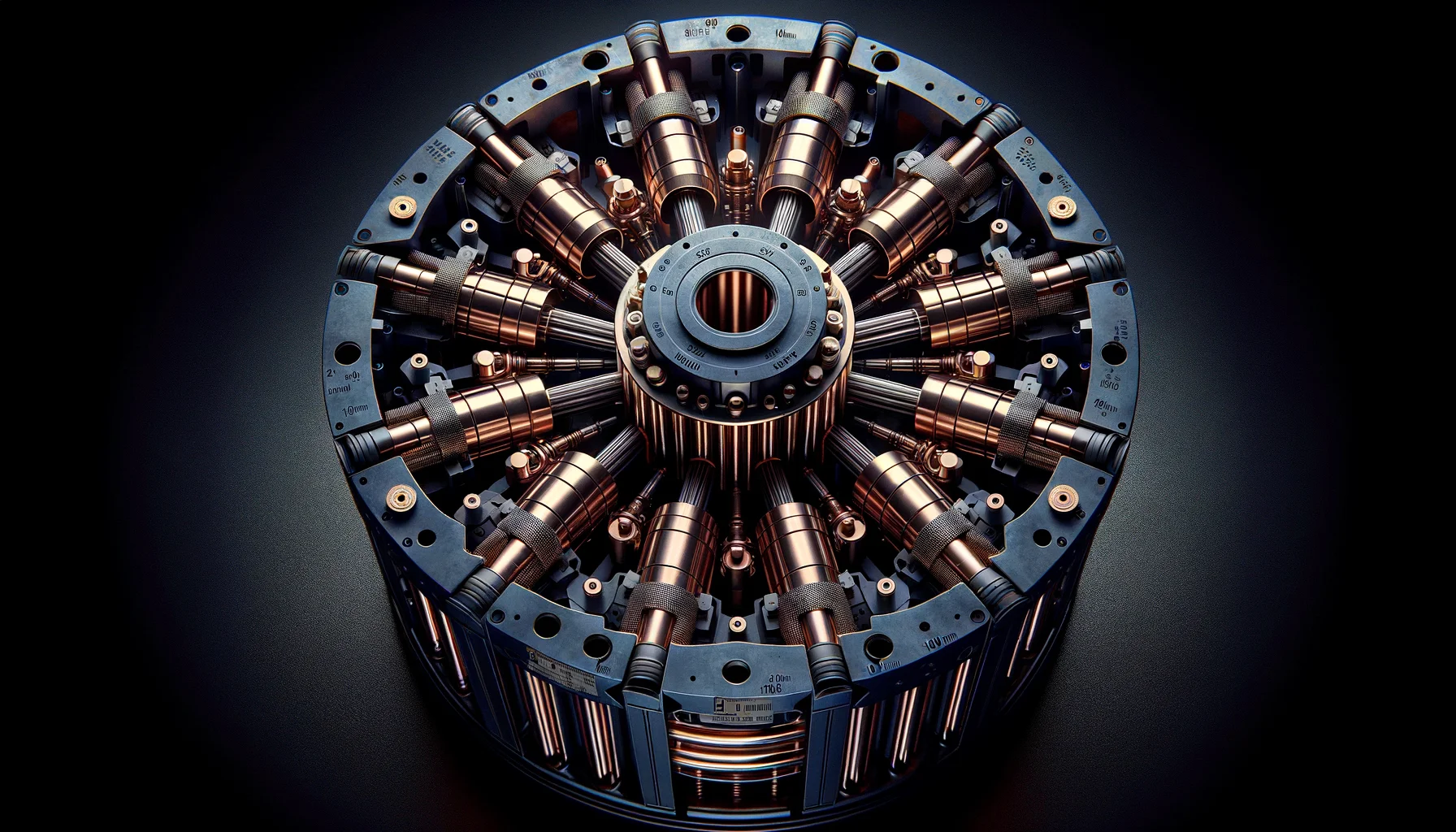
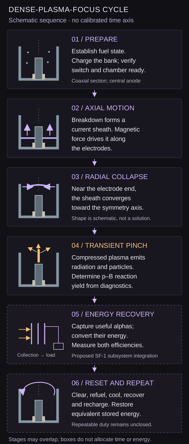
The proposed core uses a coaxial dense-plasma-focus arrangement. A bank discharge forms a current sheath that travels along the electrodes and compresses toward the axis near their end. The transient pinch provides the candidate reacting region. Electrical and optical diagnostics must determine how much of the bank energy reaches that region and which ion populations produce the measured reactions.
Charged-product collection
Magnetic optics would guide a useful fraction of the alpha-particle distribution toward the recovery section. Collection efficiency is separate from electrical conversion efficiency. Loss cones, pitch-angle spread, collisions, scattering and interception on structure determine what reaches the converter.
Direct conversion
The proposed converter decelerates charged particles against electric fields and transfers energy to a load. A traveling-wave, staged arrangement is one candidate. Its acceptance must be matched to the actual energy, angle and arrival-time distributions, with space charge, secondary electrons, insulation and transient loading included.
The study conversion range is 65–75% of incident alpha energy into particle-derived gross electrical output. It is not a demonstrated efficiency for this source. Converter excitation and conditioning supplies remain in the complete electrical-input account; they are not deducted twice. Measurements with representative particle distributions precede selection of the final stage count.
04 / Calculation
One complete-cycle energy account
The reference test boundary contains the discharge system, conversion equipment and every auxiliary. Integrate meters over a complete repeating cycle, or over a complete pulse train including its recharge and recovery interval. Capacitors, magnets and other energy stores must start and end at equivalent states. A falling state of charge is not net generation.
For an open-loop characterization test, keep generated output on a separate load while external supplies feed the drive and auxiliaries. Define $E_D$ as net external drive energy: metered charging input less drive energy returned through that same supply boundary. Define $E_A$ as all other external electrical consumption and $E_G$ as gross generated electricity measured at the separate output.
Recovered drive energy reduces $E_D$ once; it is not also counted as fusion-derived output in $E_G$. If generation is recirculated during a closed-loop test, do not count that internal transfer as both fresh external input and exported output. Reconcile the separated-flow ledger with the plant's metered net import/export.
Nominal energy allocation at 50 kHz
| Quantity | Per complete cycle | At nominal repetition |
|---|---|---|
| Net external drive energy, ED | 1,000 J | 50 MW |
| Auxiliary electrical energy, EA | 200 J | 10 MW |
| Gross generated electricity, EG | 2,000 J | 100 MW |
| Net electrical output | 800 J, as required above | 40 MW nominal duty |
| Engineering gain | 1.667 | |
This allocation is not a solved discharge or pulse-power design. In particular, net drive energy is not capacitor-bank stored energy. The bank capacitance, voltage, inductance, current waveform, recovery fraction and switching losses must support the specified peak current and duty.
Calculated fusion and heat load
For an assumed alpha collection fraction of 80% and conversion fraction of 70%, producing the stated gross electricity from fusion alone requires:
The result is 3,571.429 J of fusion energy per cycle, or 178.571 MW at the nominal rate. After the 40 MW net electrical export, approximately 138.571 MW remains as non-exported energy to reject or contain, including thermal and radiative channels. This balance includes the drive and auxiliary consumption once. It is not an assertion that all non-exported energy arrives in one coolant circuit.
No secondary thermal generation is credited here. If added, it must recover a separately accounted residual energy stream rather than count the same alpha energy a second time. The heat-rejection burden belongs to the installed plant, not just the core envelope.
Count, energy yield and gain are different quantities
Detector alpha counts require corrections for background, efficiency, solid angle, transport and the energy distribution before they establish total reaction yield. For the principal three-alpha channel, an inferred total source yield gives $N_{\mathrm{reactions}}\approx N_\alpha/3$. Fusion energy is then reaction count times energy released per reaction.
A bank-referenced fusion gain, $Q_{\mathrm{bank}}=E_{\mathrm{fusion}}/E_{\mathrm{bank}}$, is distinct from the electrical engineering gain defined above. Alpha counts, alpha-count enhancement and an ion temperature are not any of these energy gains. Reporting one does not establish another.
05 / Critical assumptions
The operating envelope must close in every subsystem
| Requirement | Available basis | Remaining gap |
|---|---|---|
| Useful proton–boron yield | Measured p–B reactions and deuterium DPF behavior | Absolute p–B reaction energy per metered bank energy in the selected DPF composition and waveform, with backgrounds resolved. |
| Favorable scaling | Controlled pulsed-discharge methods | Measured yield and efficiency as current, geometry and energy vary. Independent enhancement factors cannot simply be multiplied into a reactor gain. |
| Complete 20 μs cycle | Nominal timing requirement | Chamber clearing, fuel delivery, plasma-state recovery, switch reset, recharge, heat removal and electrode condition must permit the next comparable pulse. |
| Collector and converter match | Plasma direct-converter experiments | Captured alpha energy and generated electricity measured separately with this source's particle and timing distributions. |
| Plant mass and service life | Core layout and component allowances | Installed power equipment, shielding, vacuum plant, cooling, structures and maintenance included. Core mass cannot stand in for total plant mass. |
| Stable net export | Explicit nominal energy allocation | Measured positive complete-cycle balance with uncertainty, at sustainable duty, including startup/recovery and every auxiliary. |
At 50 kHz the apparatus undergoes 180,000,000 cycles per hour. Electrode erosion, impurity accumulation, pulse quality, insulation and component fatigue therefore belong in the power specification. Pulse frequency is not useful duty unless yield and service life are retained.
Measured repetition behavior in related apparatus
A published repetitive deuterium plasma-focus experiment reports synchronized charging and triggering, current diagnostics and thermal limits: regular 0.2 Hz runs lasting two minutes, and a 1 Hz run lasting 20 seconds. Four discharges in a documented 24-shot sequence did not focus. Those observations belong to that apparatus, not SF-1, and are not a universal rate limit. They show why clock frequency, pulse quality, diagnostics and cooling must be measured together.
Digital control may coordinate bank timing, fueling and diagnostics, but it cannot supply an absent energy balance. Sensor latency, electromagnetic interference and actuator authority limit the useful feedback bandwidth. A pulse that self-terminates still leaves stored electrical energy, radiation, pressure and thermal hazards requiring engineered protection.
Integration with an atmospheric propulsion unit would require independent demonstrations of both systems and a joint installed mass and heat budget. The nominal SF-1 output is not an available power supply to Lorentz Aerospace or another division.
06 / Experimental program
Seven results required for the power-unit design
The program begins with a diagnostic discharge experiment, not the nominal full-power assembly. Tests require a qualified pulsed-power and radiation facility. Each stage records uncertainty, repeatability, complete energy flows and the condition of the hardware.
- Repeatable proton–boron yield per bank energy.
Establish absolute fusion yield with independent diagnostics, backgrounds and controls. Report capacitor-bank energy and wall-input energy separately.
- Measured scaling.
Vary current, stored energy, geometry and fueling over a controlled range. Determine where yield, impurity burden and electrical efficiency improve or saturate.
- A repetition ladder.
Proceed through 1 Hz → 10 Hz → 100 Hz → 1 kHz → 10 kHz → 50 kHz only when measured yield, pulse quality and component lifetime support the next point. Include reset, recharge, cooling and service intervals; bursts alone do not establish continuous duty.
- Alpha capture.
Measure the source energy/angular distribution and the fraction delivered to a representative converter entrance. Separate fusion alphas from other accelerated species.
- Direct electrical conversion.
Measure particle-derived electrical recovery and converter supply costs at representative pulse distributions. Establish insulation, space-charge and thermal performance under repetition.
- Integrated engineering gain above unity.
Close the complete-cycle electrical ledger with energy stores restored, auxiliaries included and recirculation counted once. Demonstrate net export beyond measurement uncertainty at a sustained operating point.
- Scale net power.
Only then increase average output while maintaining gain, lifetime, radiation control and heat rejection. The nominal 40 MW duty is the design destination, not a substitute for these measurements.